GPR

Ground penetrating radar (GPR) is one of the most common geophysical survey techniques for near-surface investigations. Advanced inversion of GPR measurements can provide a spatial resolution in the order of a few centimeters, which is interesting for many near-surface investigations.
Common limitations for high-precision inversions of GPR data are the unknown transfer functions for the signal path from the antenna into the soil, and the large effort to obtain the required large number of GPR measurements needed for tomography and thus the limited temporal resolution in monitoring applications.
To overcome these limitations, we aim to develop a scalable multi-channel tomography system with a sufficient amount of channels to allow GPR monitoring without the need for moving the antennas during the measurements. This measurement system concept enables measuring a complete tomogram within a few seconds.
Technical challenge
Compared to common GRP setups and systems, our project requirements are very challenging regarding the amount of channels, the density of antennas and the experimental integration. Therefore, major challanges are the custom design of the GPR antenna arrays and the synchronization of a few hundred ADC channels. Further challenges include the control of the system and the efficient collection and storage of the measurement data.
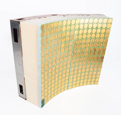
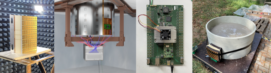
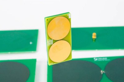
The first application of the GPR system is within a laboratory setup with a cylindrical soil column. Our scalable system contains of 39 multi-antenna tiles, each containing 64 antennas that can be used for transmission and receiving of GPR signals. Each tile has to be synchronized precisely to a central time base in order to resolve small variations in the signal travel time, that need to be translated into soil permittivity. These tiles include the data acqusition (DAQ) hardware, containing a pulse generator, multiple ADCs and a CPU for initial processing capabilities. The 64 antennas are connected to the DAQ by a multiplexer. A Tx/Rx mode switch controls whether an antenna should send or receive signals.
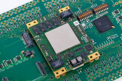
The DAQ is realized by RF-system-on-modules (RF-SoM). These modules use a Xilinx chip (RF-SoC) as a core element, which contains a processing unit, a FPGA, eight ADCs and eight DACs. These modules control the clock , that synchronize with the main module as well as path on the synchronization signals to following DAQ units. They control the signal generator and receive and process the received signals. An embedded MQTT client publishes housekeeping data and measurement data. The module is connected to a Spartan FPGA that is used to control the analog circuits, i.e. the multiplexer and the programmable amplifiers.
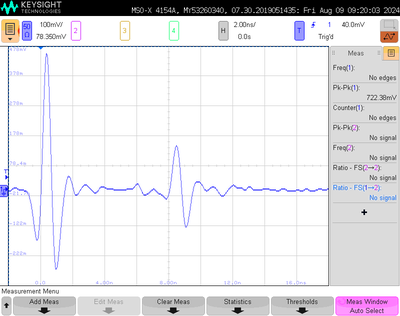
The so-called time-zero calibration of a GPR system ensures that only the travel time of the pulse within the medium is used to derive the medium properties. Additional travel times within the system need to be known and subtracted when comparing the measured signals to modelled ones in the inversion process. The common approach is to measure once with a known antenna separation and a known medium in between of the antennas. Since this is not possible in our desired setup with a real soil taken out of nature and a few thousand antennas permanently mounted to the column, a novel in situ calibration had to be developed. The calibration is based on parasitic effects within the analog circuit and makes use of the coupled Tx/Rx capability of each of our channels. More details can be found in Steinbeck et al., 2023.
The antenna design, besides synchronization and data acquisition, has a major influence on the performance of the overall GPR system. It can be very specific for each application. For the intended application, the antennas need to have a broad bandwidth combined with small size and, ideally, an isotropic radiation pattern. Due to the fixed setup, the antenna needs to provide these characteristics even when included in an antenna array. We develop these antennas in a model-based approach, meaning that we use analytical estimations, state-of-the-art electromagnetic modelling (e.g. CST by Dassault) and application-driven software (e.g. GPRmax) to optimize the antenna design. Promising designs are verified with our measurement equipment and laboratories (Keysight VNA, Spectrum analyzers, EMV chamber, etc.) in an iterative development process.
Contact

- Institute of Technology and Engineering (ITE)
Room 214